Arduino Tutorial: Detecting Light with a Light Sensing Resistor for beginners
Learn How to Use a Light Sensing Resistor with Arduino
Resistor to Detect Light with Arduino
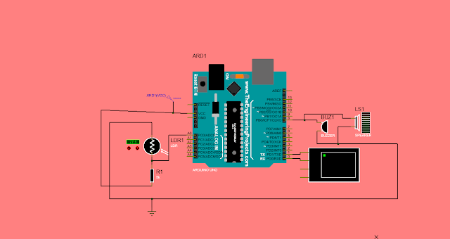
components for the circuit:1. Arduino uno
2.buzzer
3.battery
4.LDR (light dependent resistor).
Explaining the code:
The code is for an Arduino microcontroller, which is a small computer that can be programmed to interact with the physical world using sensors and actuators. In this case, the Arduino is connected to a light sensor and a buzzer.The first four lines of the code set up variables to store information that will be used later in the code. The `lightpin` variable is set to `A0`, which is the analog input pin connected to the light sensor. The `buzzpin` variable is set to `8`, which is the digital output pin connected to the buzzer. The `lightval` variable will be used to store the value read from the light sensor, and the `delaytime` variable will be used to store the amount of time the buzzer should be on and off.
The `setup` function runs once when the Arduino is turned on or reset. In this function, the `pinMode` function is used to set the `lightpin` as an input and the `buzzpin` as an output. This tells the Arduino that it should read data from the light sensor and send data to control the buzzer. The `Serial.begin(9600)` function initializes serial communication at a baud rate of 9600 so you can see what's happening in the code on your computer.
The `loop` function runs over and over again as long as the Arduino is on. In this function, the `analogRead` function is used to read the value of the light sensor and store it in the `lightval` variable. The value of `lightval` will be between 250 and 750 with higher values indicating more light.
The next line calculates how long the buzzer should be on and off based on the value of lightval. The formula is obtained using slope. We prefer the sound the buzzer makes at 1ms to 10 ms. The value of the light sensor when light is shown on it versus when light is not shown on it is 250 to 750. This can be illustrated using a graph as shown below:
So, as you can see from my ugly graph, I used the equation of a straight line when the intercept is not zero, which is (y-y1) = m(x-x1). I got ‘m’ by using the measured value of light and the value I wanted for the buzzer.it essentially determines how fast or slow the buzzer should beep based on how much light is detected by the sensor.
The `Serial.println(lightval)` function prints the value of `lightval` to the serial monitor so you can see it on your computer. This can be useful for debugging or understanding what's happening in the code.
The next three lines use the `digitalWrite` and `delay` functions to turn the buzzer on and off at a frequency determined by the value of `delaytime`. The `digitalWrite(buzzpin,HIGH)` line turns on the buzzer by sending a signal to `buzzpin`. The `delay(delaytime)` line waits for an amount of time determined by `delaytime`. The `digitalWrite(buzzpin,LOW)` line turns off the buzzer by stopping the signal to `buzzpin`. The final `delay(delaytime)` line waits for another amount of time determined by `delaytime`, then ends the loop and starts it over again from the beginning.


No comments: